Heading www.gapilot.co.uk

Build Diary 03-December-05


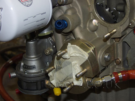
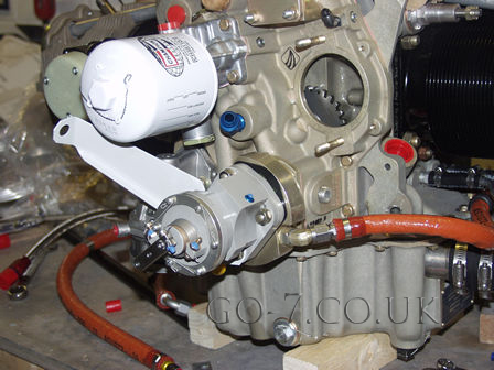
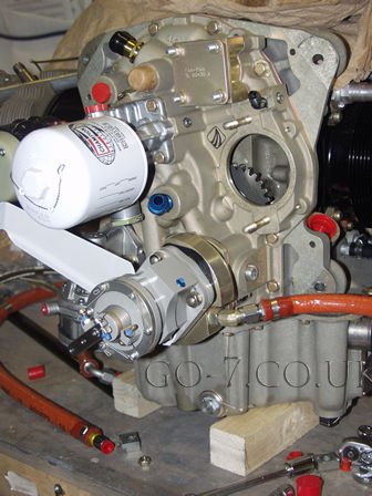
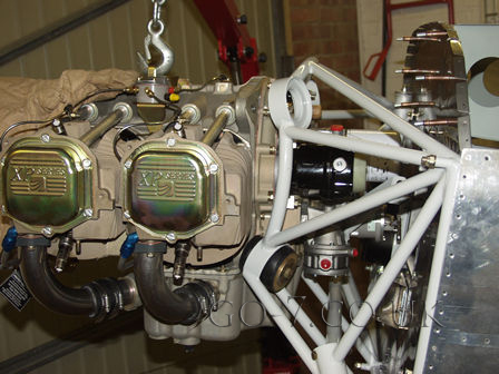
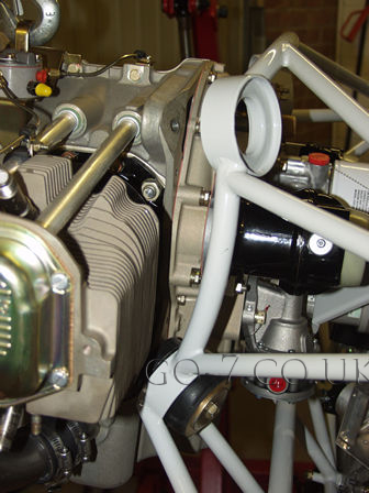
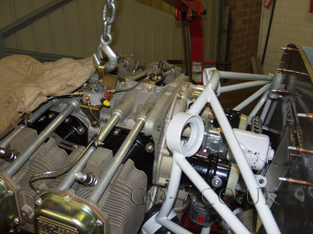
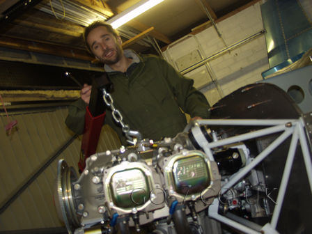
Saturday, went to the airfield this morning. Just far to much water about to fly so 
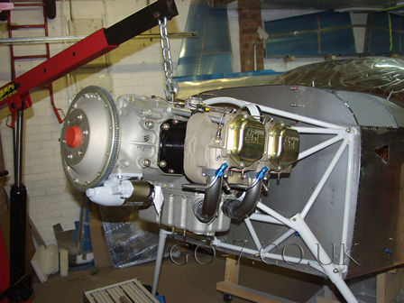
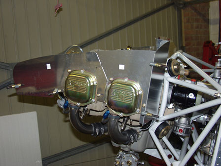
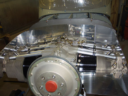
back to the workshop and fitted some parts to the rear of the engine then fitted the engine to the frame (the fuse). I fitted it in under2 hrs on my own!!

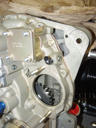
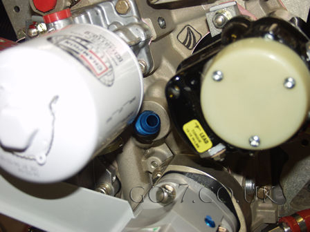
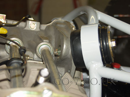
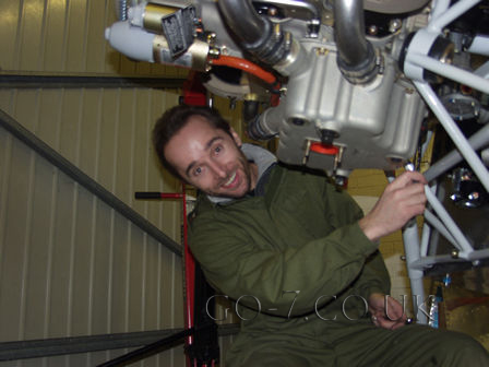
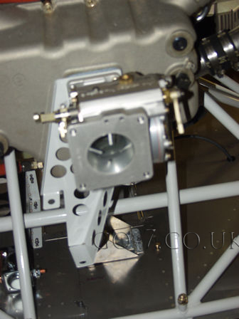
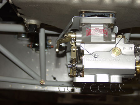
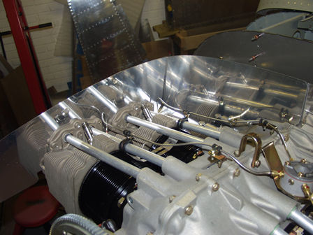
Started fitting parts to the engine, not going straightforward as this is where differences between engine types need to be resolved. See picture text......

Working on the engine - fitted the oil pressure take off on the engine. The black part below. This could have been a straight connector, however the joint has a restrictor fitted. The Vans FWF kit only has a 45 degree fitting. This is because on the Lycoming engine has the take off closer to the engine mount - the original point (Lycoming) can be seen blanked off next to the black joint below. To get the joint fitted I needed to remove the magneto.
Oil pressure take off - black joint. With original Lycoming position blanked off. If the original Lycoming position it's impossible to remove joint with engine fitted in frame.
(BLUE) 45 degree joint fitted for engine to oil cooler.
I have fitted the studs to the accessory casing. However the oil line to the front of the crank needs to be removed to fit into the engine frame.
An MT Prop govenor comes with the FWF kit.

The cable bracket comes with the prop gov' having tried the cable it appears unable to move the gov' through all the necessary travel. I will need to look into this.
Thats all the parts fitted that need to be with the magneto removed.

As this picture shows getting to the oil cooler out position with the magneto fitted will be challenging.
THE BIG DAY! Engine fitting. The engine mounts have tow sides. A soft side and a hard size. On the lower mount the soft half of the mount is against the engine. On the top mount the hard side of the mount is against the engine. Here I have started with the lower mount as suggested in the build manual.


Fitting the (looking from front) top right mount. The second from last mount. With a bit of effort the bolt went in. Notice the pust rod by the bolt head? This makes it impossible to get a ring spanner off the nut after it's been tightened!! So I ground down an old spanner thin enough to get out after the nut is tightened. It's not possible to use an open ended spanner.
The oil take off to the front of the crank pipe needed to be removed to fit the engine. But it was not possible to refit at this angle, so I had to move it to face down.
With the oil take-off at this angle it's not possible to fit the pipe, as the engine mount is in the way.
Jo came in to see what I was doing.

The next problem. The fuel flow device needs a bracket to hold the control cables - throttle and mixture.

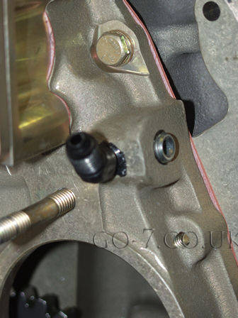
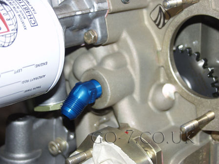
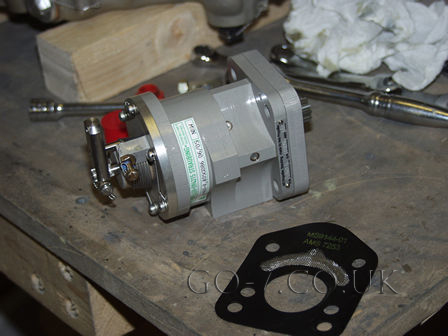
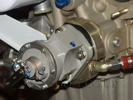
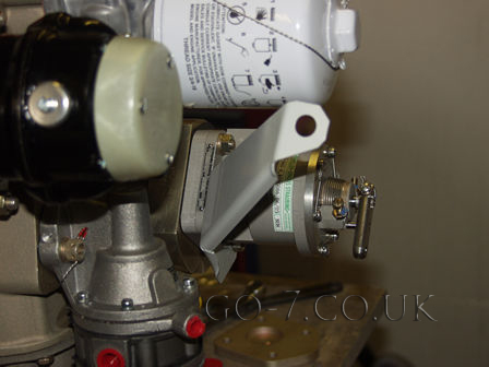
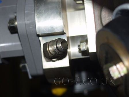
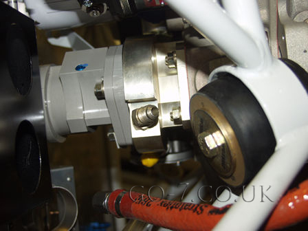
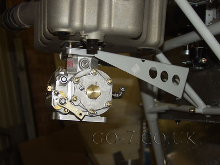
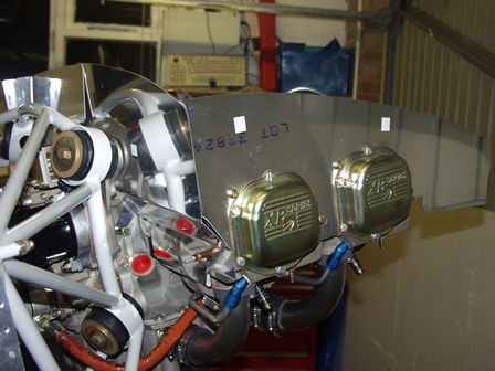
Another problem! The mixture lever will hit the airbox. This is a 3015002-1 Precision Fuel Injection servo. It should be a 3015012-1 which will reverse the mixture and allow a different arm to be fitted to operate from above instead.

As you can see in the picture the bracket appears to expect the controls are on the same side. But they are not.

I decided to move onto something else while I decide what to do about the throttle. The baffles. I had heard they could be a fiddly and take time. The bulk of the parts have gone on quite quickly although all needed some trimming and adjustment.
The oil cooler needs fitting to the right rear area. However the plans suggest this should be done after fitting the baffles seals. As I understand the plans so far - the cowling would need to be fitted first. To get the cowling fitted properly I need to have the propeller fitted! See the catch? I don't have the prop yet! I doubt I will be getting it before Christmas, and possibly not soon after........

Some adjustment needed in this area.

Images & text copyright GAPilot & Go-7. This mail is not connected to Vans Aircraft Inc. The contents of this site is the opinion of the author, not Vans Aircarft, PFA, CAA or FAA. Please check all information is correct before you act upon it.